

Why do U-bend tubes often become the most failure-prone, difficult-to-install, and leakage-sensitive components in heat exchanger or boiler projects? The core issue lies in whether wall thinning after bending, stress relief, and geometric accuracy are properly controlled-factors that directly determine long-term operational reliability.
Our ASTM A213 TP304 Stainless Steel Seamless U Bend Tube is specifically designed for high-performance heat exchange systems. To address wall thinning in the bend area, we utilize precise cold or hot bending processes, strictly controlling the thinning rate within ≤10%, ensuring that the bent section maintains sufficient pressure-bearing capacity and structural strength. After bending, all U-tubes undergo solution annealing (typically above 1040°C followed by rapid cooling), effectively relieving residual stresses generated during bending, restoring corrosion resistance, and preventing stress corrosion cracking during service.


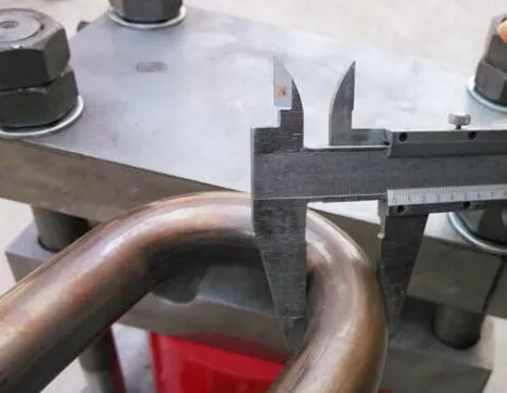
In terms of geometric control, we maintain ovality in the bend area within ≤8%, ensuring proper fit with tube sheets and support structures while avoiding installation interference or blockage. At the same time, overall dimensional tolerances strictly comply with ASTM A213 standards. The leg length and center distance of U-tubes are precisely controlled, and customized lengths can be provided based on project requirements, significantly improving on-site installation efficiency.

Specification for U-Tube: Minimum Bending Radius
| MINIMUM BENDING RADIUS IN MM | |||||||||||
| Outside Diameter | Wall Thickness | ||||||||||
| inch | 0.035 | 0.039 | 0.049 | 0.059 | 0.065 | 0.079 | 0.083 | 0.095 | 0.109 | ||
| mm | 0.89 | 1.1 | 1.24 | 1.5 | 1.65 | 2 | 2.11 | 2.41 | 2.77 | ||
| BWG | 20 | 18 | 16 | 14 | 13 | 12 | |||||
| inch | mm | ||||||||||
| 0.625 | 15.9 | 40 | 32 | 24 | 24 | 24 | 32 | ||||
| 0.63 | 16 | 40 | 32 | 24 | 24 | 24 | 32 | ||||
| 0.75 | 19.05 | 38 | 28.5 | 28.5 | 28.5 | 28.5 | 28.5 | 38 | |||
| 0.787 | 20 | 40 | 30 | 30.3 | 30 | 30 | 30.5 | 35 | |||
| 0.839 | 21.3 | 42.5 | 32 | 32 | 32 | 32 | 32 | ||||
| 0.984 | 25 | 50 | 38 | 38 | 38 | 38 | 50 | ||||
| 1 | 25.4 | 51 | 38 | 38 | 38 | 38 | 51 | ||||
| 1.181 | 30 | 60 | 45 | 45 | 45 | 45 | 60 | ||||
| 1.252 | 31.8 | 65 | 48 | 48 | 48 | 48 | 65 | ||||
| Initial Length:Maximum Lengths of 30 m can be supplied on request | |||||||||||
| Bending Radius: Maximum 1000mm | |||||||||||
| The above sizes are those most frequently used,other sizes can be produced upon request. | |||||||||||
BWG Gauge Weight Chart for Tube Wall thickness (Heat Exchanger Tube & Condensers Tube & Boilier Tube)
| Outside Diameter | Stainless Steel Tube Weight (kg/m) | ||||||||||||||
| Birmingham wire Gauge Conversion from BWG to mm | |||||||||||||||
| 25 BWG | 22 BWG | 21 BWG | 20 BWG | 19 BWG | 18 BWG | 17 BWG | 16 BWG | 15 BWG | 14 BWG | 13 BWG | 12 BWG | 11 BWG | 10 BWG | ||
| mm | inch | 0.51 mm | 0.71 mm | 0.81 mm | 0.89 mm | 1.07 mm | 1.24 mm | 1.47 mm | 1.65 mm | 1.83 mm | 2.11 mm | 2.41 mm | 2.77 mm | 3.05 mm | 3.4 mm |
| 6.35 | 1/4 | 0.074 | 0.1 | 0.112 | 0.121 | 0.141 | 0.158 | 0.179 | 0.193 | 0.206 | - | - | - | - | - |
| 9.53 | 3/8 | 0.115 | 0.156 | 0.176 | 0.192 | 0.225 | 0.256 | 0.295 | 0.324 | 0.351 | 0.39 | 0.427 | 0.466 | - | - |
| 12.7 | 1/2 | - | 0.212 | 0.24 | 0.262 | 0.31 | 0.354 | 0.411 | 0.454 | 0.496 | 0.557 | 0.618 | 0.685 | 0.733 | 0.788 |
| 15.88 | 5/8 | - | 0.268 | 0.304 | 0.332 | 0.395 | 0.452 | 0.528 | 0.585 | 0.64 | 0.724 | 0.809 | 0.905 | 0.975 | 1.057 |
| 19.05 | 3/4 | - | 0.324 | 0.368 | 0.403 | 0.479 | 0.55 | 0.644 | 0.715 | 0.785 | 0.89 | 0.999 | 1.123 | 1.216 | 1.325 |
| 25.4 | 1 | - | - | 0.496 | 0.543 | 0.648 | 0.746 | 0.876 | 0.976 | 1.074 | 1.224 | 1.38 | 1.561 | 1.698 | 1.863 |
| 31.75 | 1 1/4 | - | - | - | 0.684 | 0.818 | 0.942 | 1.109 | 1.237 | 1.364 | 1.558 | 1.761 | 2 | 2.18 | 2.401 |
| 38.1 | 1 1/2 | - | - | - | - | 0.987 | 1.139 | 1.341 | 1.498 | 1.653 | 1.892 | 2.143 | 2.438 | 2.663 | 2.939 |
| 44.5 | 1 3/4 | - | - | - | - | 1.158 | 1.336 | 1.576 | 1.761 | 1.945 | 2.228 | 2.527 | 2.879 | 3.149 | 3.481 |
| 50.8 | 2 | - | - | - | - | 1.325 | 1.531 | 1.806 | 2.02 | 2.232 | 2.559 | 2.905 | 3.314 | 3.628 | 4.014 |
| 63.5 | 2 1/2 | - | - | - | - | - | - | 2.271 | 2.542 | 2.811 | 3.227 | 3.667 | 4.19 | 4.593 | 5.09 |
| 76.2 | 3 | - | - | - | - | - | - | - | 3.064 | 3.39 | 3.894 | 4.43 | 5.067 | 5.558 | 6.166 |
| 88.9 | 3 1/2 | - | - | - | - | - | - | - | 3.586 | 3.969 | 4.562 | 5.192 | 5.943 | 6.522 | 7.241 |
| 101.6 | 4 | - | - | - | - | - | - | - | 4.108 | 4.548 | 5.229 | 5.955 | 6.819 | 7.487 | 8.317 |
| 114.3 | 4 1/2 | - | - | - | - | - | - | - | - | - | 5.897 | 6.717 | 7.696 | 8.452 | 9.393 |
Applications:
Petrochemical & Chemical: Used in refineries, chemical plants, and other facilities for heat transfer and cooling processes.
Power Generation: Employed in both conventional and nuclear power plants for condenser cooling and heat recovery systems.
HVAC: Utilized in air conditioning and refrigeration units for efficient heat exchange.
Food & Beverage/Pharmaceutical: Applied in processing equipment for tasks like pasteurization, sterilization, and cooling of products.
How to test ASTM A213/ASME SA213 TP304 U bend tube?
ASTM A213/ASME SA213 TP304 U bend tubes are used in critical applications where they are exposed to high temperatures and pressures.
1. Hydrostatic Test: A hydrostatic test is a pressure test that is performed on U bend tubes to check for leaks and to ensure that the tube can withstand the required pressure. The test involves filling the tube with water and pressurizing it to a specified level for a specific duration.
2. Flaring Test: A flaring test is performed to check the ductility of the U bend tube. The test involves flaring the end of the tube to a specific diameter without cracking.
3. Hardness Test: A hardness test is performed to determine the hardness of the U bend tube. The test is usually performed using a Rockwell or Brinell hardness tester.
4. Tensile Test: A tensile test is performed to determine the tensile strength of the U bend tube. The test involves applying a tensile load to a specimen of the tube and measuring the amount of deformation.

Plastic End Caps: The two straight ends of the U-tubes must be fitted with tight-fitting plastic plugs or caps.
Frame Requirements: Sturdy solid wood or plywood must be used; the base shall feature sufficient reinforcement ribs to support tube bundles ranging from 6 to 12 meters in length.
Export Standards: If cross-border transport is involved, the timber must undergo ISPM 15 fumigation treatment and bear the IPPC mark.

